
 Home
Home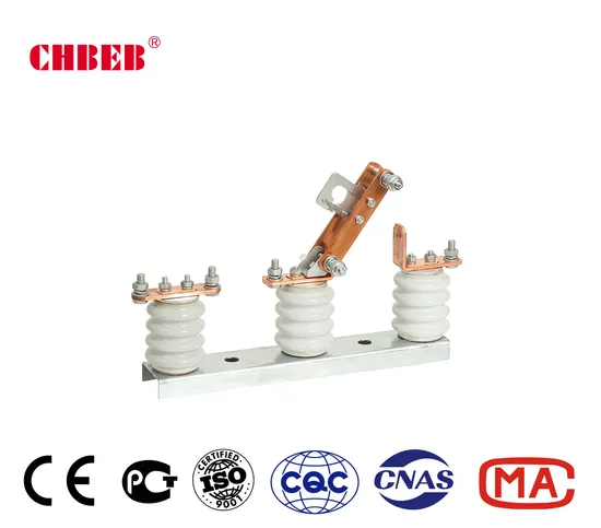
High Medium Voltage Outdoor Isolation Switch Load Break Disconnectors
- Overview
- Product Description
- Detailed Photos
- Product Parameters
- Certifications
Basic Info.
| Model NO. | (H)GWBEB |
| Installation | Outdoor High-voltage |
| Operation | Manual/Electric/Pneumatic/Hydraulic |
| Grounding Mode | According to Customer Requirements |
| Movement Mode | According to Customer Requirements |
| Number of Poles | According to Customer Requirements |
| Grounding | According to Customer Requirements |
| Series | Two |
| Run | According to Customer Requirements |
| Switching Mode | According to Customer Requirements |
| Common Model | Gw9 |
| Structure of Operating | According to Customer Requirements |
| Certification | ISO, RoHS, CE |
| Brand | Chbeb |
| Customizable | OEM/According to Customer Requirements |
| Transport Package | Standard Shipping Packing |
| Specification | 45*55*38mm |
| Trademark | CHBEB |
| Origin | China |
| HS Code | 853530900 |
| Production Capacity | 5000 PCS/Quarter |
Product Description

The (H)GWBEB type outdoor high-voltage isolation switch, also known as an isolation disconnect switch, is meticulously engineered for seamless integration into 10(12, 15, 24)kV high voltage power transmission and distribution systems. It adeptly manages the opening and closing of single-phase or three-phase circuits with voltage present but without any load, ensuring operational efficiency and reliability.
Designed for single-phase use in three-phase line systems, this switch is renowned for its uncomplicated design, cost-effectiveness, and user-friendly operation. It offers a versatile range of rated currents, including 200, 400, 600, 800, 1000, and 1250 amps. The switches are composed of a robust base, durable post insulators, conductive elements, and a mechanical section, all working in harmony. The gate knife structure, featuring two conductive blades per phase, is instrumental in circuit operations. External compression springs on both sides ensure optimal contact pressure, adjustable by altering spring height. The switch's operations, facilitated by an insulated hook stick, include a self-locking mechanism for enhanced safety and reliability.
Working Environment:
The switch is designed for altitudes not exceeding 1000 meters;
It operates efficiently in ambient temperatures with a maximum limit of +40°C and a minimum of -30°C;
Capable of withstanding outdoor wind speeds not exceeding 35 meters/second;
Suitable for seismic activities with intensity not exceeding 8 degrees; the installation site should be free from frequent severe vibrations to ensure continued functionality.
The chosen installation site should be devoid of harmful gases, chemical deposits, salt mist, dust, dirt, or any other explosive or corrosive substances that could adversely affect the switch's insulation and conductivity.
Note:
WHEN THE ABOVE NORMAL USE CONDITIONS ARE EXCEEDED, USERS ARE ENCOURAGED TO CONSULT AND NEGOTIATE WITH THE COMPANY FOR CUSTOM SOLUTIONS.
Installation, Use and Adjustment
Pre-installation work
- Meticulously remove any dust and dirt from parts, and thoroughly clean the surface of the insulating porcelain bottle for optimal performance.
- Ensure the wiring surface of the ground screw is scrubbed clean for secure electrical connections.
- Apply a protective layer of industrial Vaseline to the rotating parts and contact areas to reduce friction and wear.
- Inspect the contact surface and adjust the compression spring's height to ensure the contact pressure aligns with Table II for ideal operation.
- This switch is specifically suited for hoisting applications and is intended for use in conjunction with transformers on the line.
- The switch's rated current spans from 200 to 400 ampere hours with three mounting holes for installation. For currents of 600-1000A, three mounting holes are typically used.
It is advised to conduct annual inspections of the following components to maintain optimal functionality:
Thoroughly remove all dirt from conductive parts, contact surfaces, and the surface of insulating porcelain bottles to ensure cleanliness and efficiency.
Inspect all components for signs of damage, with special attention to the insulating porcelain bottle for any damage or cracks that may compromise its integrity.
Examine the contact surfaces of conductive parts to verify they are in good condition for reliable operation.


Product Parameters
| The main technical parameters | Table I | |||||||||
| Model | Rated voltage | Rated current | kA | 10 seconds thermal stable current | ||||||
| peak | Valid values | |||||||||
| (H)GW | 10 | 200 | 5 | 9 | 5 | |||||
| 400 | 21 | 15 | 10 | |||||||
| 600 | 35 | 25 | 14 | |||||||
| 630 | 35 | 25 | 14 | |||||||
| 800 | 35 | 25 | 14 | |||||||
| 1000 | 50 | 35 | 20 | |||||||
| Contact force parameters | Table II | |||||||||
| Model | Rated current(A) | contact pressure(kgf) | ||||||||
| (H)GW | 5 | 9 | ||||||||
| 21 | 15 | |||||||||
| 35 | 25 | |||||||||
| 35 | 25 | |||||||||
| 35 | 25 | |||||||||
| 50 | 35 | |||||||||